MEAM 5270 COMSOL k-ω SST Team of 3

F1 Airfoil Failure Analysis:
1969 Lotus 49B

A CFD and FEA investigation into the catastrophic rear wing structural failures at the 1969 Spanish Grand Prix — reconstructing the aerodynamic loads that broke Graham Hill's Lotus 49B, using a COMSOL k-ω SST model of the NACA 0012 airfoil swept across a full operating envelope.

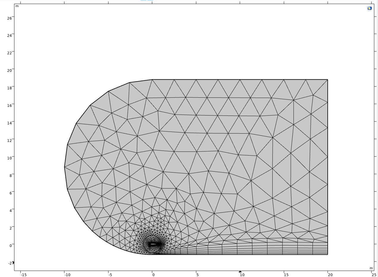
COMSOL mesh — C-shaped domain with refined elements around NACA 0012 airfoil
COMSOL mesh — C-shaped domain with local refinement around the NACA 0012 airfoil
Project Summary

On May 4, 1969, Graham Hill's Lotus 49B suffered a catastrophic rear wing collapse during the Spanish Grand Prix at Montjuic Park — the supporting strut failed under extreme aerodynamic load, sending Hill into the barriers. Similar failures occurred across multiple teams that season, prompting an immediate ban on high-mounted wings before the Monaco Grand Prix two weeks later.

This study reconstructs the loading conditions that caused these failures using 2D CFD in COMSOL Multiphysics. A NACA 0012 airfoil profile (the most likely candidate for the Lotus 49B, whose exact profile was never published) was modeled in a C-shaped domain with a k-ω SST turbulence model, swept across angles of attack from −20° to +20° at race-representative conditions (90 m/s, Re = 6.125×10&sup6;). The resulting forces were applied to a simplified single-strut FBD using known 2024 aluminum strut dimensions.

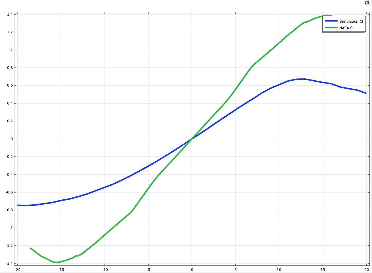
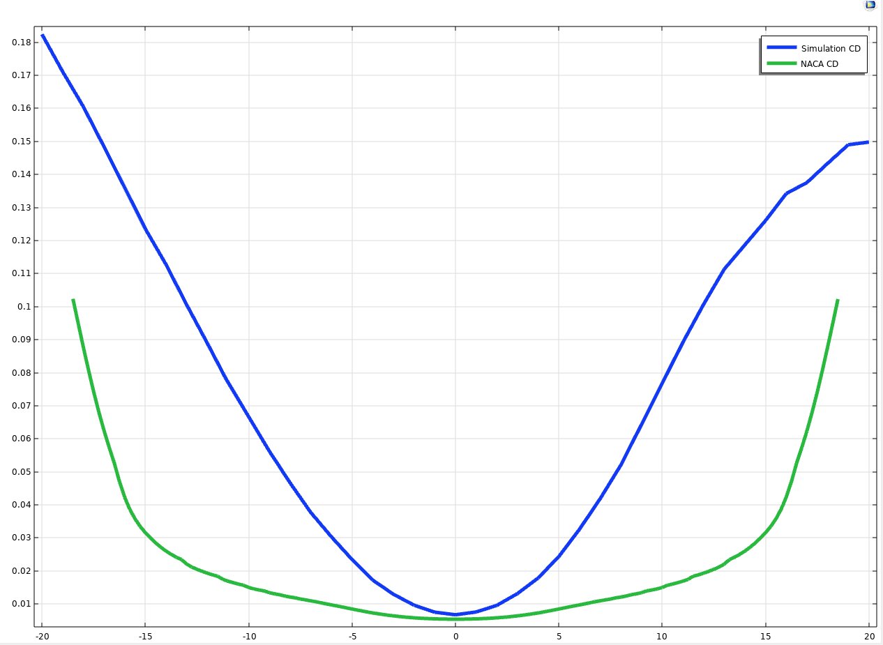
Validation against published NACA 0012 data confirmed stall at 16° and linear-region agreement, establishing confidence in the structural loading calculations.

CourseMEAM 5270 — Mechanics of Solids
TeamJason Chen, Solomon Gonzalez, Leo Tan
AirfoilNACA 0012
Turbulence modelk-ω SST
Freestream velocity90 m/s (~324 km/h)
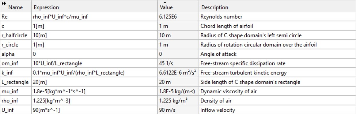
Reynolds number6.125 × 10&sup6;
AoA sweep−20° to +20°, 1° increments
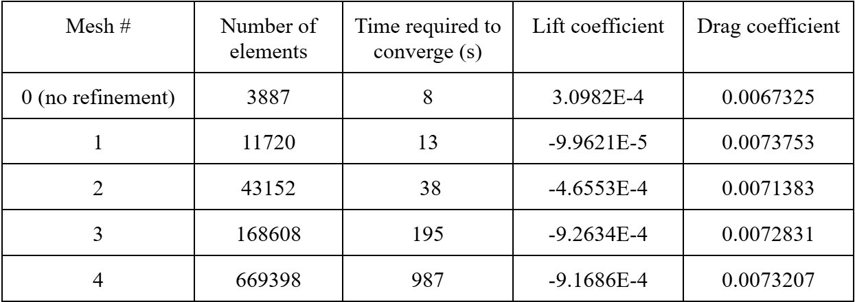
Mesh levels5 (3,887 → 669,398 elements)
Strut material2024 aluminum (E=70 GPa, σ_y=324 MPa)
What I Built
// CFD setup
Boundary Conditions & Domain
Set up the full COMSOL boundary condition configuration: no-slip on the airfoil surface, inflow velocity at left/top edges (90 m/s), outflow at right boundary, and moving-ground no-slip at the bottom to simulate realistic ground-effect interactions under the F1 car.
// parametric study
AoA Variable Sweep
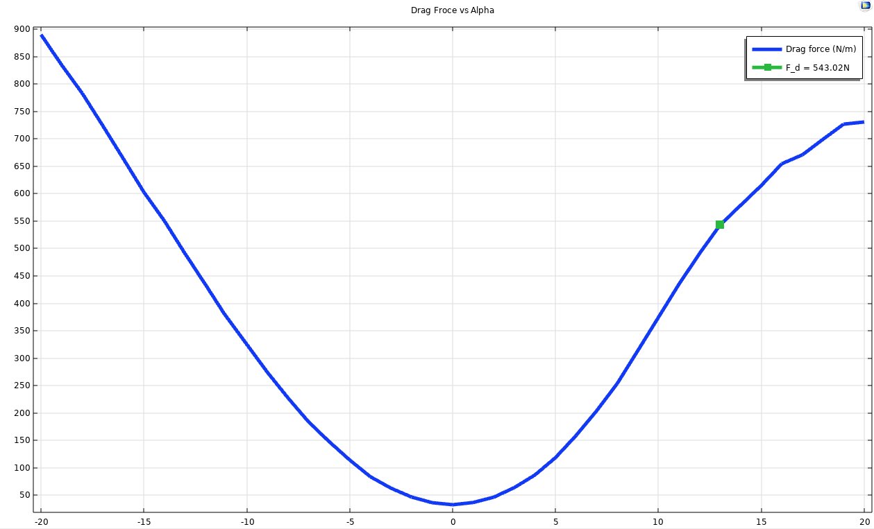
Designed and ran the full angle-of-attack sweep from −20° to +20° in 1° increments using COMSOL's parametric solver — 41 individual simulations with convergence criteria of 1e-6 and a maximum of 300 iterations each.
// structural
Failure Mode Analysis
Performed the FEA stress-driven failure study on the wing-and-strut assembly — built the FBD, derived the moment at the beam support using M_beam = M_CG + 1.2·F_D, and checked both buckling and bending failure modes against 2024 aluminum material properties.
// validation
NACA 0012 Validation
Validated the simulation against NACA airfoil database data at Re = 1,000,000 (lowered inflow to 15 m/s for matching). Confirmed stall angle at 16°, near-zero lift at 0°, and symmetric negative-AoA behavior — all matching published experimental results.
// mesh study
Mesh Convergence Study
Supported the 5-level mesh convergence study using a local refinement bounding box (4m×2m) around the airfoil. Analyzed relative errors in C_L and C_D vs. mesh 4 reference, justifying mesh #1 (11,720 elements) as the optimal balance for the full parameter sweep.
// analysis
Ground-Effect Analysis
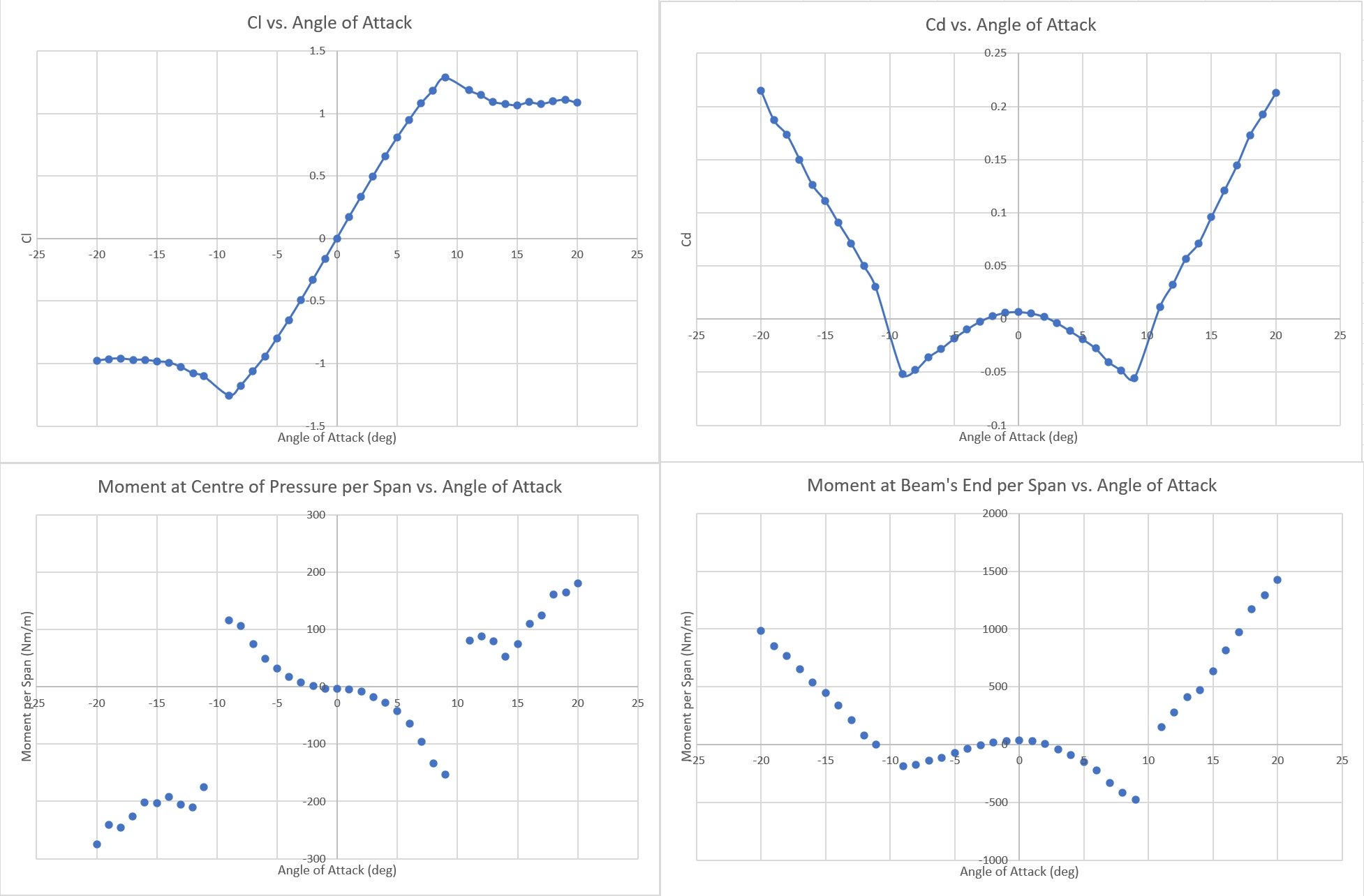
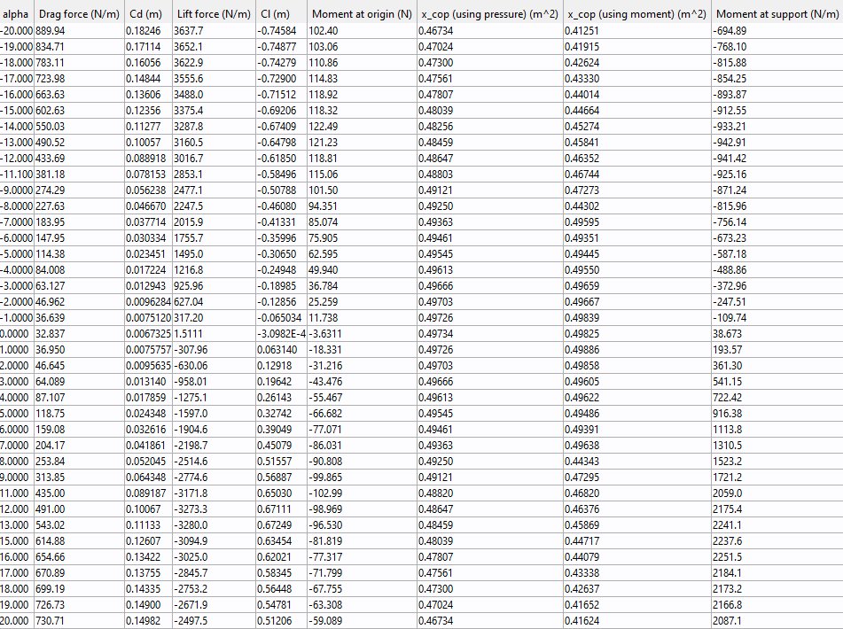
Analyzed the near-ground configuration separately from freestream validation — identified ground-effect distortion in the C_L curve (non-symmetric around α=0), elevated drag floor, and the sharp moment transition between α=9° and α=10° that likely triggered the historical failure.
Simulation Framework
// step 01
C-shaped domain with nested rotation subdomain
A C-shaped computational domain (10c upstream, 10c vertical, 20c downstream) encapsulates an inner circular subdomain of radius c centered on the NACA 0012 quarter-chord. The airfoil rotates within the circular subdomain without altering inflow boundary conditions — enabling the full AoA sweep with a consistent reference frame.
// step 02
k-ω SST turbulence model
Selected for its hybrid near-wall/free-stream behavior: k-ω formulation in the viscous sublayer for accurate wall stress, switching to k-ε in the free stream for stability. Superior prediction of adverse pressure gradients and boundary layer separation makes it particularly well-suited for airfoil stall analysis.
// step 03
5-level mesh convergence
Progressive local refinement in a 4m×2m bounding box around the airfoil, from 3,887 elements (mesh 0) to 669,398 (mesh 4). Lift converges much faster than drag — consistent with CFD best practices, as lift is governed by pressure distribution while drag requires finer near-wall resolution. Mesh 1 (11,720 elements) selected for the AoA sweep.
// step 04
Structural failure analysis
Forces from the CFD peak-load case were applied to a simplified single-strut model (L=1.2m, b=0.01m, h=0.07m, 2024 aluminum). Moment at the beam support was calculated as M_beam = M_CG + 1.2·F_D. Both compressive buckling (Euler critical load) and bending failure modes were evaluated against the material yield strength.
Key Findings
16°
Predicted stall angle
Matching published NACA data
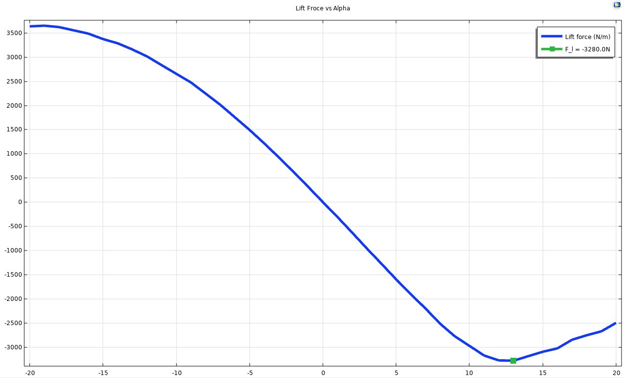
−3,280 N
Peak downforce at α=13°
At 90 m/s, Re = 6.125×10&sup6;
2,241 Nm/m
Peak moment at strut base
At α=13° ground-effect config
α = 9°→10°
Critical moment transition
Sharp nonlinear jump under ground effect
Critical Finding — Failure Mechanism
A one-degree AoA deviation could have triggered catastrophic failure

The most significant result of this study was the identification of a sharp, nonlinear moment transition between α=9° and α=10° under near-ground conditions. In the ground-effect configuration at 90 m/s, the moment at the strut base increases dramatically over this one-degree range — far exceeding the smooth behavior predicted by classical NACA wind tunnel data.

It is likely that the Lotus 49B was designed to operate near α=9°, the point of maximum downforce (C_L peak). However, any small operational deviation — a track bump, a steering input cresting a rise, or an asymmetric load — could shift the wing past that threshold, inducing a large, sudden torque spike that the slender 2024 aluminum struts were never designed to withstand.

The ground-effect C_L curve is also non-symmetric around zero, with early stall-like behavior and elevated drag compared to freestream NACA results. This is attributed to boundary layer growth along the ground wall, increased pressure build-up, and early flow separation — effects entirely absent from the wind tunnel data the designers would have used in 1969.

Validation Result
Stall angle and linear-region lift confirmed against NACA 0012 database

At Re = 1,000,000 (15 m/s inflow), the simulation matched the NACA 0012 database closely in the −5° to +5° range, with nearly identical slopes. The predicted stall angle of 16° matches the published experimental value exactly. Maximum C_L was slightly lower than the reference (1.25 vs. 1.4), attributed to the limitations of steady-state RANS modeling at high angles of attack.

Drag coefficients were systematically overestimated (C_D ≈ 0.04 at 0° vs. published 0.007), consistent with known RANS skin friction over-prediction. However, the relative trends across angles of attack remain valid for structural loading comparisons, and the lift forces — the primary driver of strut bending — were accurately captured.
Technologies Used
COMSOL Multiphysics k-ω SST CFD FEA NACA 0012 Profile Parametric Sweep Mesh Convergence Euler Buckling Analysis Ground Effect Modeling Force & Moment Integration 2024 Aluminum FBD